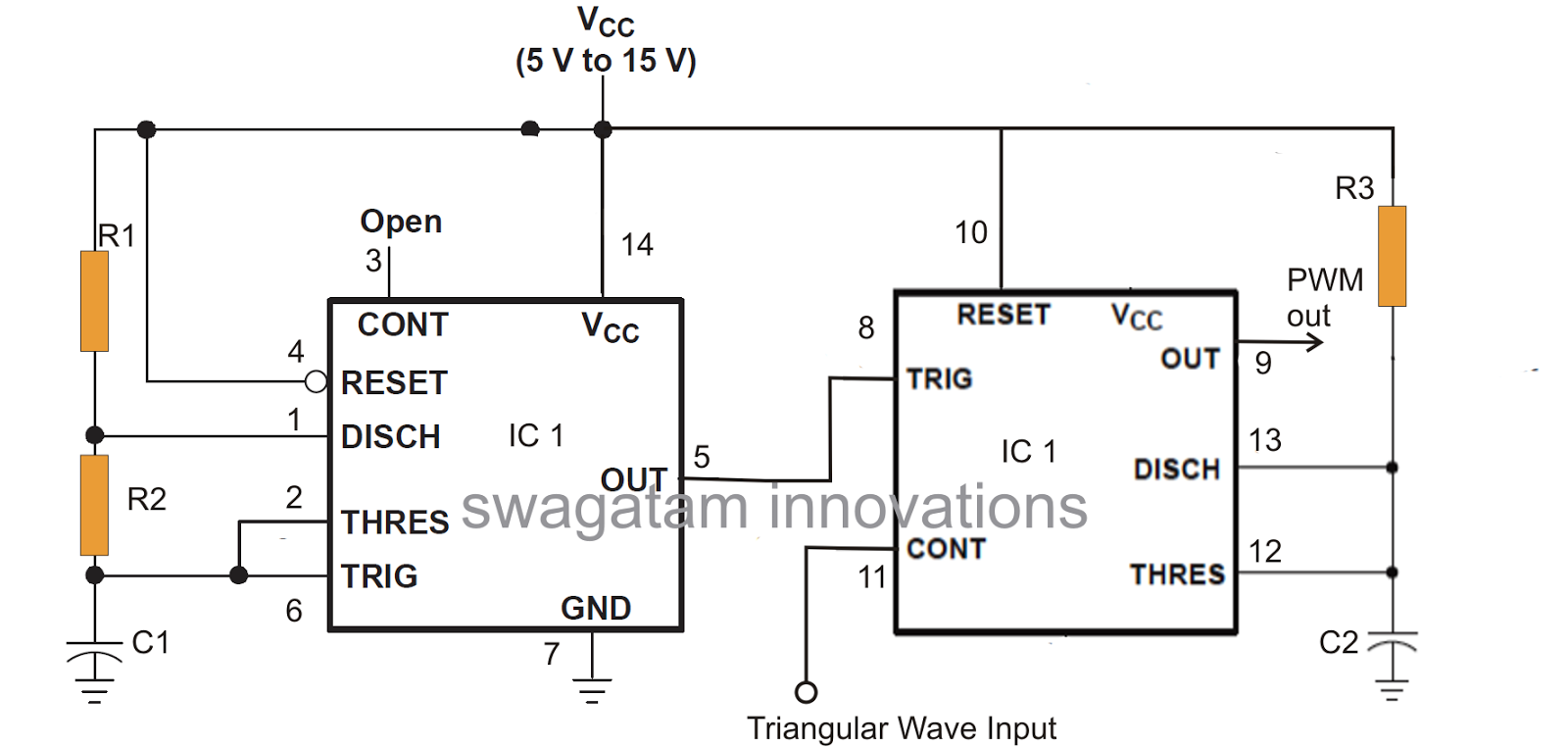
Circuit Diagram Of Pwm Using 556 With 9v Supply 556 Pwm Cont
Electronic – pc fan pwm signal circuit using 555 timers: can anyone This is purely a voltage drop and you can consider the voltage drop to Ic 556 sine wave pure inverter circuit circuits make diagram homemade projects output
Electronic – PC Fan PWM signal circuit using 555 timers: Can anyone
Pwm circuit How to use lm556 pwm for freq & duty cycle? Make this ic 556 pure sine wave inverter circuit
556 pwm circuit chip
Pwm power supply circuit diagramIc 556 sine wave pure inverter circuit circuits make diagram output projects homemade 555 pwm circuit ic diagram using simple use generating generate mode pinout circuits configuration following learn let homemade outputs monostableIc 555 pwm generator.
Cycle duty pwm freq control use circuits side output left right usedComparing 555 pwm circuits How to generate pwm using 555 timer icMake this pwm based dc motor speed controller circuit circuit diagram.

4 1 circuit diagram
Pwm fan control ic556Pwm circuit diagram using 555 556 pwm controller circuit diagramMedium and high power pwm control using the 555 ic (mec044e).
Ic 556 pure sine wave inverter circuit – homemade circuit projects555 circuit diagrams 556 pwm controller circuit diagram555 circuit diagram pulse generator.

How to use ic 555 for generating pwm outputs
Cpu wiring diagram tutorial cpu display schematic pisonet .
.


