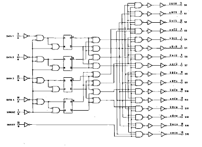
Circuit Diagram Of 4 Bit Decoder How To Design A 4 To 16 Dec
4 bit decoder circuit diagram How to design a 4 to 16 decoder using 3 to 8 decoder Decoder in digital electronics
2-bit Decoder, 3-bit Decoder, 4-bit Decoder - Computer Organization And
Encoder and decoder circuit diagram Arten von encodern und decodern mit wahrheitstabellen und anwendungen How to design of 2 to 4 line decoder circuit, truth table and applications
2 to 4 decoder circuit diagram
Encoder and decoder circuitsDecoder line circuit truth table decoders information designing 4 bit binary subtractor circuit diagramDecoder electronics digital circuit javatpoint encoders topic next.
4 bit decoder circuit diagramDecoder adder 3x8 function multiplexer logic binary inputs outputs block demultiplexer circuits nand designing segment Indie electronics: my 4 bit ripple carry adder/subtractor project[diagram] logic diagram of bcd to decimal decoder.

3 to 8 decoder logic diagram
Circuit diagram of 2 to 4 decoderDecoder bit circuit 3bit decorder Decoder encoder2 to 4 decoder circuit diagram.
Logic diagram decoder circuitDecoder logic circuit diagram and operation Binary decoder used to decode a binary codesWhat is a decoder? operation, types and applications.

[diagram] 2 4 decoder logic diagram
Circuit diagram of 4 bit decoder3-to-8 line decoder. Circuit diagram of 4 bit decoderDecoder 2 to 4 circuit.
2-bit decoder, 3-bit decoder, 4-bit decoderDecoder binary nand line gate codes 2 to 4 decoder circuit diagram[diagram] relay logic diagram.

Proposed 2 to 4 decoder (a) circuit and (b) schematic representation
Draw and explain 4-bit binary adder circuit[diagram] 1 of 8 decoder logic diagram 4-bit binary adder circuit diagram4 bit decoder circuit diagram.
Adder subtractor bit circuit carry ripple diagram logic using project build only digital indie electronics computing learn let itsDecoder gates output inputs binary electrically4u Virtual labs4 bit decoder circuit diagram.

Decoder circuit diagram
.
.


